AI, ML, Development + Cisco Learning Blog Learning about Machine Learning, Artificial Intelligence, related devlopment topics and formerly Routing and Switching, Datacenter, Security and other topics, CCIE #23664, Frank Wagner

8. August 2006

802.1x authentication using cisco switches

Filed under: Security — ocsic @ 10:18

There are several ways for authenticate a switchport. This could be neccessary, if you want to make sure, the client is the client you want on the lan. Normaly you would say your environment is worth for trusting, but maybe you should be more suspicous on your neighbours. Don’t trust to easy. Well this is network security.

The 802.1x authentications is a client server based mechanism. So you need a device that can speak IEEE 802.1x-compliant Software so it can answer the authentication server requests.

The switch just acts like a proxy. There are several different way in combining the switch an the client for port and/or vlan authentication.
Here is the setup for a switch forwarding the clients request for authentication on a specific port.

aaa new-model
aaa authentication login default none
aaa authentication dot1x default group radius
!
dot1x system-auth-control
!
interface FastEthernet0/1
switchport mode access
dot1x port-control auto
!
interface FastEthernet0/2
switchport mode access
dot1x port-control auto
!
!
radius-server host 192.168.1.100
radius-server key PASSWORD

Source:

http://www.cisco.com/univercd/cc/td/doc/product/lan/c3550/12225see/scg/sw8021x.htm

Etherchannel for an 3550 Catalyst and maybe others

Filed under: Bridging + Switching — ocsic @ 05:50

Etherchannel is for fault tollerance and you can use it to increase the bandwidth. You can bound up to to eight interface to an eitherchannel. All interfaces must be the same speed and all have to be configured as layer 2 or layer 3 interfaces. If one interface fails, the traffic is automatically redirected to the other interfaces.

Etherchannel can be configured in one of these modes:

  • Port Aggregation Protocol (PAgP)
  • Link Aggregation Control Protocol (LACP)
  • On mode

You can setup an etherchannel in two different ways. You can set it up as layer 2 or a layer 3 interface.

There are four etherchannel modes:

  • active
  • auto
  • desirable
  • passive

Only in auto and desireable switches are exchanging PAgP packets. Only in active and passive switches are exchanging packets in LACP mode.

The following cominations are allowed for forming an etherchannel:

PAgP:

auto – desirable

desirable – auto

desirable – desirable

LACP:

active – active

active – passive

There is also on – mode, witch is for not negotiating the etherchannel between the devices. Could be usefull if one device does not support PAgP or LACP.

Here is an configuration example, where Switch 1 is trying actively to convert this link in an etherchannel, while Switch 2 will respond to these requests. The Link is also configured as a trunk link with dot1q:

Switch1:

Ports fa0/13 – 15 to be configured in the etherchannel.

sw3(config-if)#int range fa0/13 – 15
sw3(config-if-range)#switchport mode trunk

sw3(config-if-range)#channel-group 1 mode desirable
Creating a port-channel interface Port-channel 1
02:19:53: %LINK-3-UPDOWN: Interface Port-channel1, changed state to up
02:19:54: %LINEPROTO-5-UPDOWN: Line protocol on Interface Port-channel1, changed state to up
Switch2:

SW2(config)#int range fa0/13 – 15
SW2(config-if-range)#switchport trunk encapsulation dot1q

SW2(config-if-range)#switchport mode trunk
SW2(config-if-range)#channel-group 1 mode auto
Creating a port-channel interface Port-channel 1
01:39:20: %LINK-3-UPDOWN: Interface Port-channel1, changed state to up
01:39:21: %LINEPROTO-5-UPDOWN: Line protocol on Interface Port-channel1, changed state to up

Here are some commands for verifying etherchannel functions. CDP is working over etherchannel, so if you see your other switch, then etherchannel will work.
To verify the etherchannel use the commands:

show etherchannel

show pagp

show lacp

show cdp

Source:

http://www.cisco.com/univercd/cc/td/doc/product/lan/c3550/12225see/scg/swethchl.htm

http://www.cisco.com/en/US/products/hw/switches/ps607/products_configuration_example09186a0080094789.shtml

7. August 2006

debugging frame-relay

Filed under: Frame-Relay — ocsic @ 06:13

To debug frame-relay there are several possibilities.

The first useful command is:

sh frame-relay pvc

With this command you could list all currently configured pvc’s.

This may look like:

DLCI = 314, DLCI USAGE = LOCAL, PVC STATUS = ACTIVE, INTERFACE = Serial1/1

input pkts 1 output pkts 0 in bytes 30
out bytes 0 dropped pkts 0 in pkts dropped 0
out pkts dropped 0 out bytes dropped 0
in FECN pkts 0 in BECN pkts 0 out FECN pkts 0
out BECN pkts 0 in DE pkts 0 out DE pkts 0
out bcast pkts 0 out bcast bytes 0
5 minute input rate 0 bits/sec, 0 packets/sec
5 minute output rate 0 bits/sec, 0 packets/sec
pvc create time 00:23:07, last time pvc status changed 00:23:07
Note the pcv ACTIVE status. This indicates the pvc is up and running and lmi messages are being send to and from the frame-relay switch .

The PVC can have four possible states. These are shown by the PVC STATUS field as follows:

  • ACTIVE – PVC is up and functioning normally.
  • INACTIVE – PVC is not up end-to-end. This may be because either there is no mapping (or incorrect mapping) for the local DLCI in the frame-relay cloud or the remote end of the PVC is Deleted.
  • DELETED – Either the Local Management Interface (LMI) is not exchanged between the router and the local switch, or the switch does not have DLCI configured on the local switch.
  • STATIC – no keepalive configured on the frame-relay interface of the router.

It’s also a good idea, if you have change frame-relay your configuration on an interface, to reload the router. Just to make sure, no old configuration settings are interferring.
The DLCI status can be one of the following:

The DLCI USAGE field contains one of the following entries:

  • SWITCHED – the router or access server is used as a switch.
  • LOCAL – the router or access server is used as data terminal equipment (DTE).
  • UNUSED – the data-link connection identifier (DLCI) is not referenced by user-entered configuration commands on the router.

To find out something about the lmi layer 2 communications between the frame-relay devices you can use:

debug frame-relay lmi

This could also show some information about the satus of the frame-relay link:

*Mar 1 08:51:53.615: Serial1/1(out): StEnq, myseq 43, yourseen 41, DTE up
*Mar 1 08:51:53.615: datagramstart = 0x7B00854, datagramsize = 13
*Mar 1 08:51:53.615: FR encap = 0xFCF10309
*Mar 1 08:51:53.615: 00 75 01 01 00 03 02 2B 29
*Mar 1 08:51:53.615:
*Mar 1 08:51:53.631: Serial1/1(in): Status, myseq 43, pak size 45
*Mar 1 08:51:53.631: RT IE 1, length 1, type 0
*Mar 1 08:51:53.631: KA IE 3, length 2, yourseq 42, myseq 43
*Mar 1 08:51:53.631: PVC IE 0x7 , length 0x6 , dlci 311, status 0x0 , bw 0
*Mar 1 08:51:53.631: PVC IE 0x7 , length 0x6 , dlci 312, status 0x0 , bw 0
*Mar 1 08:51:53.631: PVC IE 0x7 , length 0x6 , dlci 314, status 0x2 , bw 0
R3#
*Mar 1 08:51:53.631: PVC IE 0x7 , length 0x6 , dlci 315, status 0x2 , bw 0

As you can see the lines with „status 0x0“ or „status 0x2“ this could tell you:

Notice the status of „DLCI 314“ in the output above. The possible values of the status field are explained below:

  1. 0x0-Added/inactive means that the switch has this DLCI programmed but for some reason (such as the other end of this PVC is down), it is not usable.
  2. 0x2-Added/active means the Frame Relay switch has the DLCI and everything is operational. You can start sending it traffic with this DLCI in the header.
  3. 0x3-0x3 is a combination of an active status (0x2) and the RNR (or r-bit) that is set (0x1). This means that the switch – or a particular queue on the switch – for this PVC is backed up, and you stop transmitting in case frames are spilled.
  4. 0x4-Deleted means that the Frame Relay switch doesn’t have this DLCI programmed for the router. But it was programmed at some point in the past. This could also be caused by the DLCIs being reversed on the router, or by the PVC being deleted by the telco in the Frame Relay cloud. Configuring a DLCI (that the switch doesn’t have) will show up as a 0x4.
  5. 0x8-New/inactive
  6. 0x0a-New/active

List your static and dynamic mappings and show also witch link is active or has a differnt status:

show frame-relay map

Serial0/0 (up): ip 183.1.0.3 dlci 405(0x195,0x6450), static,
CISCO, status deleted
Serial0/0 (up): ip 183.1.0.5 dlci 405(0x195,0x6450), static,
broadcast,
CISCO, status deleted

or for example:

Serial0/0 (up): ip 183.1.0.4 dlci 504(0x1F8,0x7C80), static,
broadcast,
CISCO, status defined, active
Serial0/0 (up): ip 54.1.1.6 dlci 504(0x1F8,0x7C80), dynamic,
broadcast,, status defined, active

Source:

http://www.cisco.com/univercd/cc/td/doc/product/software/ios120/120newft/120limit/120s/120s12/12sfrsdg.htm

http://www.cisco.com/en/US/tech/tk713/tk237/technologies_tech_note09186a008014f8a7.shtml
6. August 2006

3550 IOS recovery

Filed under: IP and IOS Features — ocsic @ 21:04

The 3550 Catalyst switch does not have IOS recovery functions other than xmodem, when the IOS is lost due to corruption or maybe user error. You have to copy it with xmodem back to the switch. I would suggest, taking a smaller image first, because this take quite a long time. For an 3,5 MB sized image, it would take 1 hour and 10 Minutes.

Boot the switch with the missing IOS. Start the command:

switch: copy xmodem: flash:new-filename.bin

And then start Hyperterminal and send the binary file from your local harddisc via xmodem.
Source:

http://www.cisco.com/en/US/products/hw/switches/ps628/products_tech_note09186a0080169696.shtml

5. August 2006

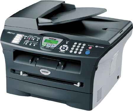
Brother 7820N als Drucker für Linux und SuSE 10.0

Filed under: Allgemein — ocsic @ 10:53

Nachdem ich mir zuerst einen Multifunktionsdrucker Samsung SCX-4100 gekauft hatte und ihn nun wieder wegen verschiedener Probleme verkauft habe, ist nun ein Neuer an der Reihe. Der Alte hat mir vom Design viel besser gefallen, aber das zählt nun mal nicht, wenn man drucken möchte und das nicht klappt. Darum habe ich mich diesmal ein vorher etwas schlauer gemacht. Ein Schmuckstück ist der neue Drucker nun wirklich nicht.
Hier ist nur die Konfiguration über den LAN Anschluss beschrieben. USB interessiert mich hier nicht, weil so gut wie alle Funktionen auch über LAN verfügbar sind. Darum habe ich den Drucker gar nicht erst per USB angeschlosse. Selbst das Scannen übers Netz ist möglich. Unten ist ein Link für den Scanbetrieb über das Netz. Aber ich werde das bestimmt auch noch mal etwas näher beschreiben, wenn ich die Zeit dazu gefunden habe und es
auch selber eingerichtet habe.

MCF7820N

Der Drucker kann sowohl am USB-Anschluss und natürlich über das LAN mit Linux angesprochen werden. Da ich auch SUSE 10 einsetze, gebe ich hier mal meine Konfiguration für den LAN-Zugriff wieder:1. Drucker einrichten und mit gültiger IP versorgen. Das ist gut im Handbuch von Brother beschrieben. Falls möglich, kannst Du den Drucker auch via DHCP konfigurieren.

2. Anpingen als ersten Test der Erreichbarkeit.

3. YaST -> Hardware -> Drucker aufrufen.

a) „Hinzufügen“ wählen (ggf. bei der Frage nach Queues diese verneinen)
b) In der Auswahl „Anderes Setup“ und „Weiter“
c) Druckertyp „Anderer Drucker (URI)“ wählen und „Weiter“
d) Anschluß „http://nnn.nnn.nnn.nnn“ entsprechend Deiner Drucker-IP setzen und „Weiter“
e) Name etc. sinnvoll eingeben und die Option „lokales Filtern“ aktivieren und „Weiter“, noch keinen Test durchführen 🙂
f) Zur Auswahl des Druckermodells nun „PPD-Datei zur Datenbank hinzufügen“, „Lokale PPD-Datei“ wählen… die Datei heisst BR7820_2.ppd und ist auf der Treiber CD zu finden.
g) Anschliessend unter Hersteller „Brother“ und unter Modell „MFC-7820N BRScript3“ wählen und „Weiter“
h) Nun kann ein Test nicht schaden 🙂
i) ggf. weitere Optionen anpassen und testen

Mit zweimaligem „OK“ abschliessen und fleissig drucken…

Den Scanner übers Netz zu betreiben, ist auch relativ einfach umzusetzten. Es reicht sane/xsane zu installieren und das Packet brscan2-0.2.1-0.i386.rpm (akutelle nehmen). Nach der Anleitung richtet man den Drucker mit einer IP Adresse ein:


brsaneconfig2 -a name=NAME model=MODEL-NAME ip=xx.xx.xx.xx

z.B:

brsaneconfig2 -a name=SCANNERNAME modem=MFC-7820N ip=192.168.1.44

Dann sollte es schon möglich sein, sobald man xsane startet über’s Netz zu drucken.

Source:

http://solutions.brother.com/linux/sol/printer/linux/sane_install-net.html

Remove empty lines with sed from a configuration

Filed under: Tips / Hints — ocsic @ 05:53

If you want to remove all empty lines from a config file, you can use sed on unix system. Use with the regular expression:

sed ‚/^$/d/‘ config-file > new-file

Source:

http://www.cornerstonemag.com/sed/


How to configure a Windows XP to Pix 501 connection over PPTP

Filed under: pix — ocsic @ 02:52

Setup:

PIX 501 setup

Some things to keep clear before you can configure your pix. You should add yourself to the PDM (Pix device manager) access. This can be done for example with:

http 192.168.200.0 255.255.255.0 inside

If your coming from subnet 192.168.200.0 on the inside interface to connect to your PDM.

If every thing is setup and interfaces have their addresses you can connect to your pix with https: https://192.168.200.1.

It will bring you to many different login screens …

PIX 501 setup

Here you can see, until now there are only two interfaces defined. Interface inside and interface outside. It’s important for the pix to understand, that you logically sit in the middle of the firewall. The pix can’t route, it just controlls packets from one interface to the other. A packet never can leave the interface it came from. It must leave the other interface. So also every rule you set up, must contain two different interfaces.

To see for example icmp ping’s, turn on debugging on the pix with:

debug icmp trace

to turn it off again use:

undebug all

As this is clear now, i start to configure the pix for VPN access.

First you should set up an IP Pool the pix can give address from to setup the VPN Clients.

PIX501 IP Pool

Setting up the range for addresse you could give to the clients. Be carefull not to lease addresses that yre already used. So it’s the best to use a range:

PIX501 IP Pool address range

After that you can setup a user and the PPTP (Point to Point Tunneling Protocol) Connection for the XP Client.

PIX 501 setup PPTP

Don’t forgett to enable the VPDN access on the outside interface.

After that you should add one user:

PIX 501 setup user add

That enough for now.

You should configure the XP connection now.

Go to your XP client and start network configuration and the assistent to add e new connection. Use „Connection with network or office, VPN“. Just use the defaults. It should work.
Source:

http://www.cisco.com/en/US/products/hw/vpndevc/ps2030/products_configuration_example09186a0080094a5a.shtml#tshoot

http://www.cisco.com/warp/public/707/cmatrix.shtml

4. August 2006

loading configurations with copy and paste and over TFTP

Filed under: Tips / Hints — ocsic @ 15:01

It’s quite easy that you can load a configurations into your router. You can for example load the config over TFTP oder you can just copy the config with copy and paste from another terminal.

It’s neccessary that you go into „conf t“ mode.

So if you then just put your configuration from the textfile in your editor into your clipboard, then you can copy it into your terminalwindow and you will see that all commands are set in a row. After this your device is configured.

It’s also possible to load the configuration over TFTP. Of course you need an TFTP Server. Search google to find one, matching your operating system.

Then you can copy a configuration file from the TFTP server directly into mem of the device and into running-config. It looks like:

copy tftp running-config

or for example to

copy tftp nvram:startup-config

to overwrite the startup configuration.

You can list available local configs with:

dir nvram:

As a result you could see:

Router#dir nvram:
Directory of nvram:/

29 -rw- 1410 startup-config
30 —- 5 private-config
1 -rw- 0 ifIndex-table

32762 bytes total (30273 bytes free)
Router#

You might have problems with hyperterminal and copy and paste also. It could be possbile to set the charcter dely from 10ms to 200ms. This could work with swollowed characters.

3. August 2006

configuring portfast, STP, DHCP Client Problem

Filed under: Bridging + Switching — ocsic @ 13:46

If you setup a switch it might be a good idea to set all ports by default to portfast. But take care, this could also lead to a lot of trouble if you don’t know what you’re doing. To set all ports by default to portfast use:

spanning-tree portfast default

This stops the switch from using spanning tree on all ports. And ports are up in a few seconds.
Each port on a switch using Spanning-Tree Protocol exists in one of the following five states:

  • Blocking
  • Listening
  • Learning
  • Forwarding
  • Disabled

A port moves through these five states as follows:

  • From initialization to blocking
  • From blocking to listening or to disabled
  • From listening to learning or to disabled
  • From learning to forwarding or to disabled
  • From forwarding to disabled

The port always goes through these stats first.

Here is an example from a „debug spanning-tree events“ output, how long these states take. I just moved port fa0/3 in another vlan, and it would start the STP algorithm again.
00:55:55: STP: VLAN0013 Fa0/3 -> listening
00:56:10: STP: VLAN0013 Fa0/3 -> learning
00:56:25: STP: VLAN0013 Fa0/3 -> forwarding

So it take 30 seconds for a port to be available again.

With normal PC oder Server Ports, where it’s not possible to get a switching loop, it’s best to turn on portfast. Sometime DHCP client’s boot faster than the switchport is up. Then clients won’t get an IP address. The will still try to get one, but this will be delayed. So with portfast, this does not happen.

But portfast should be configured with care. If it’s not clear what kind of device will be connected, then better leave the cisco default setting.
Source:

http://www.cisco.com/univercd/cc/td/doc/product/rtrmgmt/sw_ntman/cwsimain/cwsi2/cwsiug2/vlan2/stpapp.htm

CCIE Routing and Switching Lab Exam Blueprint

Filed under: Certification — ocsic @ 11:50

http://www.cisco.com/web/learning/le3/ccie/rs/lab_exam_blueprint.html

Now i’m working on the Lab exam. It’s been quite a task to take this an get 80% from 100% to pass the exam. I will schedule the exam in Bruessels (Belgium, Europe). It will cost $1512 which is quite more than in the USA. I have to send the mony in US Dollars, so the bank will also charge me a fee for the money exchange. Well, that’s a lot of money. And i know it’s worth it, but i also hope i will make it. 🙂

So here ist the actual Blueprint of the Lab:

  • Bridging and Switching
    1. Frame relay
    2. Catalyst configuration: VLANs, VTP, STP, trunk, management, features, advanced configuration, Layer 3
  • IP IGP Routing
    1. OSPF
    2. EIGRP
    3. RIPv2
    4. IPv6
    5. GRE
    6. ODR
    7. Filtering, redistribution, summarization and other advanced features
  • BGP
    1. IBGP
    2. EBGP
    3. Filtering, redistribution, summarization, synchronization, attributes and other advanced features
  • IP and IOS Features
    1. IP addressing
    2. DHCP
    3. HSRP
    4. IP services
    5. IOS user interfaces
    6. System management
    7. NAT
    8. NTP
    9. SNMP
    10. RMON
    11. Accounting
  • IP Multicast
    1. PIM, bi-directional PIM
    2. MSDP
    3. Multicast tools, source specific multicast
    4. DVMRP
    5. Anycast
  • QoS
    1. Quality of service solutions
    2. Classification
    3. Congestion management, congestion avoidance
    4. Policing and shaping
    5. Signaling
    6. Link efficiency mechanisms
    7. Modular QoS command line
  • Security
    1. AAA
    2. Security server protocols
    3. Traffic filtering and firewalls
    4. Access lists
    5. Routing protocols security, catalyst security
    6. Other security features
  • « Newer PostsOlder Posts »

    Powered by WordPress