AI, ML, Development + Cisco Learning Blog Learning about Machine Learning, Artificial Intelligence, related devlopment topics and formerly Routing and Switching, Datacenter, Security and other topics, CCIE #23664, Frank Wagner

29. November 2008

How to receive logging/traps with Linux from your dynamips with syslog-ng/snmptrapd

Filed under: Allgemein,IP and IOS Features,services — ocsic @ 20:06

What are traps and informs and is it possible to have a NMS (Network Managment System) on your Linux box to receive those messages? Cisco Works is also NMS, you might try this also, it’s possible to install it under VMWare, i had some trouble with 3.1 on Windows 2003 Server Enterprise SP2 though. Complaining always about not enough space on drive c:, however i expanded the disc to have more than 25GB of free space. Still no success. So i got to the point, where i dropped LMS and tried to use already present programs on my Linux box. Would like to see LMS also on my VMWare maybe later.

First make sure you have connectivity to the outside world from your dynamips. Here is a link to an more detailed description http://blog.sazza.de/?p=355. In short you need a local interface that can be bridged. You create a bridged interface and setup this with IP adressing. I use a VMWare interface for this bridged interface. Here is my script:

ifconfig vmnet7 0.0.0.0
ifconfig vmnet7 down
brctl addbr br0
ifconfig br0 10.0.0.1 netmask 255.255.255.0
brctl addif br0 vmnet7
brctl addif br0 tap0
ifconfig br0 up
ifconfig tap0 up
ifconfig vmnet7 up
The tap0 is created from your dynamips.net file. Is use Router1’s secound FastEthernt Interface:

[[Router R1]]
model = 3725
console = 2001
autostart = False
slot2 = NM-1FE-TX
slot1 = NM-4T
F0/0 = SW1 F1/1
F0/1 = NIO_tap:tap0
Now i can use R1 F0/1 for connections to the outside world.

Check your syslog-ng configuration file, to enable a socket your syslog server listens to port 514/udp:

/etc/syslog-ng/syslog-ng.conf

source src {
#
# include internal syslog-ng messages
# note: the internal() soure is required!
#
internal();

#
# the default log socket for local logging:
#
unix-dgram(„/dev/log“);

#
# uncomment to process log messages from network:
#
udp(ip(„0.0.0.0“) port(514));
};

Then restart your syslog daemon by issuing „/ect/init.d/syslog restart“. Make sure you can see the socket listening with

hostname:/usr/share/snmp/mibs # netstat -lun
Proto Recv-Q Send-Q Local Address Foreign Address State
udp 0 0 0.0.0.0:514 0.0.0.0:*
udp 0 0 0.0.0.0:162 0.0.0.0:*
udp 6624 0 0.0.0.0:68 0.0.0.0:*
udp 0 0 0.0.0.0:69 0.0.0.0:*

You might want do add port 514/tcp for syslog also listening to tcp logging messages. You can also log from your cisco router to any tcp port with:

R2(config)# logging host 10.0.0.1 transport tcp port 514

After this your system is able to recieve syslog messages und will log it into /var/log/messages for example. Check with „tail -f /var/log/messages“. Configure logging from a router with:

R2(config)# logging host 10.0.0.1

and produce some logging messages.

Next make sure that your local firewall does not block logging packets to your host.

You need at least ports:

514/udp

514/tcp

162/udp

At this point on your linux box start your

# snmptrapd -fa

You should have net-snmp-5.x.x installed (check with „rpm -qa | grep net-snmp“). This daemon also needs some kind of access configuration:

cat /etc/snmp/snmptrapd.conf

authCommunity log,execute,net CISCO
logoption f /var/log/snmptrapd.log
logoption s 2

/etc/snmp/snmpd.conf

mibs +ALL

Where CISCO is your community string. This is for SNMP v1 and v2c.

But you might want to download a list of MIBS from cisco first, to have snmptrapd support all kinds of cisco mibs. You can download them from ftp://ftp.cisco.com/pub/mibs/v1/v1.tar.gz and ftp://ftp.cisco.com/pub/mibs/v2/v2.tar.gz.

Just copy them to /usr/share/snmp/mibs (find out your mibs directory with „net-snmp-config –snmpconfpath“, where mibs should be a subdirectory, under your path for example /usr/share/snmp).

You should now be able to receive those mibs in your logfile /var/log/snmptrapd.log.

for example:

Nov 29 17:19:12 hostname snmptrapd[5824]: 10.0.0.2: Enterprise Specific Trap (.1) Uptime: 0:26:44.80, SNMPv2-SMI::enterprises.9.9.43.1.1.6.1.3.18 = INTEGER: 1, SNMPv2-SMI::enterprises.9.9.43.1.1.6.1.4.18 = INTEGER: 2, SNMPv2-SMI::enterprises.9.9.43.1.1.6.1.5.18 = INTEGER: 3

Or do an snmpwalk:

# snmpwalk -v2c -c CISCO 10.0.0.2

Reload your Cisco router with snmpset:

First enable system-reload:

snmp-server community CISCO RW
snmp-server system-shutdown

Then set the router ro reload (note dynamips router instance will crash, since reloading the router is only supported by dynagen console):

snmpset -c CISCO -v 2c 155.1.0.2  .1.3.6.1.4.1.9.2.9.9.0 i 2

Source:

http://www.net-snmp.org/wiki/index.php/TUT:Configuring_snmptrapd

http://www.net-snmp.org/wiki/index.php/TUT:Configuring_snmptrapd_to_receive_SNMPv3_notifications

http://www.net-snmp.org/wiki/index.php/TUT:Configuring_snmptrapd_to_parse_MIBS_from_3rd_party_Vendors

http://www.net-snmp.org/wiki/index.php/TUT:Using_and_loading_MIBS
http://tools.cisco.com/ITDIT/MIBS/servlet/index

22. November 2008

Implementing route reflectors and avoid loops with cluster-id or originator-id

Filed under: BGP — ocsic @ 22:56

What is a route reflector? What is a cluster-id or originator-id and why should i need id?

If you start google for cluster-id it will not bring up many explanations about what is a clusters in bgp. However it’s quite simple. Because you can have multiple route reflectors inside one AS and this might break the normal AS path loop prevention mechanism. So normally AS path takes care of loop, but inside the AS it’s done with cluster-id and originator-id.

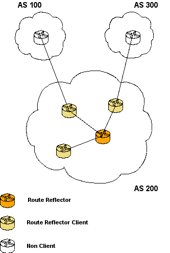
Let’s start with a route reflector. In BGP you would need a full mesh for all iBGP client peerings, to have routes propagated from client to client. Route reflection overcomes the need for a full mesh. The Route reflector reflects routes coming from a client to his route reflector clients.

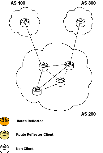
Here a sample full mesh configuration within AS 200:

BGP full mesh


Here is a replaced full mesh example with one route reflector, which copies all updated to his clients. So if an update from AS100 is received it’s send to the route reflector and the route reflector copied the update to all of it’s clients:


Make sure next hop is reachable from within the peer. In case of this example, if no next-hop-self is configured from route reflector clients to the route reflector, the next hop for routes coming into AS 200 are pointing to AS100 and as AS300 gateways. This might be a problem for AS200 RR’s, if next hop self is not reachable via a local route.

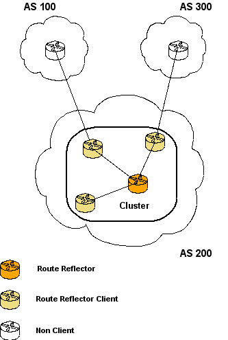
The cluster is defined by the route reflector and the route reflector client(s). The cluster id will be the router reflector client if unset (for ex. 192.168.1.1). Or the cluster ID can be set with the „bgp cluster-id [number]“ command. So here one cluster is formed:


There are several way’s in configuring route reflector and clients in this scenario. It could be a demand that more than one route reflector should be available for redundancy. If in the above scenario the route reflector fails, there is no way to cope with the situation.

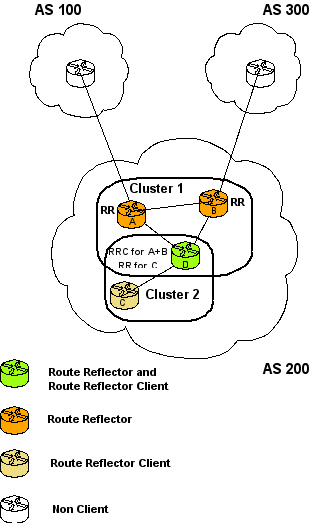
So it might be necessary to have more than one route reflector in the AS. A possible solution would be:

cluster id

Cluster id is not passed between different sub asses inside the same confederation. The cluster id can avoid unwanted traffic by denying updates, here for example, if you set „bgp cluster-id 1“ on both router A and router B, they would deny accepting updates from each other, when they receive updates with the same cluster-id.

Updates are not needed because of the hierarchical route reflector setup. Since if an update come from router C, it will be propagated to A and B. Since A and B are from their perspective „None Clients“ to each other, cluster-id comes into place. Using the same cluster-id on both, will deny updates being accepted.

Example for „debug ip bgp 135.1.12.4 updates“ on Router B if Router C is sending a new prefix and Router B is recieving the update from Router A (135.1.12.4) also (assuming A and B have the same cluster-id configured). Clusterlist is the inside AS path replacement, for avoiding routing loops. As can be seen here clusterlist holds cluster-id 1 and cluster-id 2. Cluster-id 1 is configured for both A and B, as cluster-id 2 is configured on router D. Originator ID 2.2.2.2 is router C in this example:


*Mar 1 05:40:29.650: BGP(0): 135.1.12.4 rcv UPDATE w/ attr: nexthop 135.1.13.3, origin i, localpref 100, metric 0, originator 2.2.2.2, clusterlist 0.0.0.1 0.0.0.2, path , community , extended community

*Mar 1 05:40:29.658: BGP(0): 135.1.12.4 rcv UPDATE about 1.1.1.0/24 — DENIED due to: reflected from the same cluster;

The originator id is the last step, after cluster id has not effect, in preventing updates being sent in loops. At least, when the originator recieves his own update, then it will be dropped. If cluster-id is not by „bgp cluster-id [number]“ then, it will be set by the route-reflector-client sending updates to non clients with it’s own router-id.

Source:

Internet Routing Architectures, CiscoPress, P. 268ff

RFC2796, Route Reflection, http://www.faqs.org/rfcs/rfc2796.html

http://www.cisco.com/en/US/tech/tk365/technologies_tech_note09186a00800c95bb.shtml

9. November 2008

Link Fragmentation and Interleave / LFI / FRF.12

Filed under: Frame-Relay,QoS — ocsic @ 18:58

If a packet is sent over a link, the packet delayed due to serialization. Bigger packets need more time to get over the link, than smaller packets. If a 1500 bytes packet is in the transit, a small 150 bytes packet has to wait.

Here LFI can be used to solve the problem of bigger packets blocking smaller, for example voice packets, to long, and let them being sent before the whole 1500 bytes packet is completely being sent over the link.

The definition of packet is, that it includes the Layer 3 header information and the end-user-data, namely the payload. A frame is a packet, but includes also Layer 2 information header and trailer.

While fragmenting frames, the router will chop the 1500 byte frame possibly into two frames, which had to include again the header and trailer information in each new fragmented frame.

Make sure you configure „frame-relay fragment“ on both sides of the PVC. If not, one side will definetly have problems in recognizing the fragmented traffic. If only one side fragments the traffic and the other side will not defragment it, it will just drop all fragmented traffic coming over the DLCI.

A value of 80 kpbs recommended fragmentation size to every 64 kbps bandwidth. So 256 kbps interface bandwidth, means a fragment size of 320 kbps on this link.

Note: For interleaving to work, both fragmentation and the low-latency queueing policy must be configured with shaping disabled.

Example:

access-list 101 match ip any host 1.0.0.2

class-map voice

match access-group 101

policy-map llq

class voice

priority 64

class video

bandwidth 32

interface serial 1/0

ip address 1.0.0.1 255.0.0.0

encapsulation frame-relay

frame-relay fragment 80 end-to-end

bandwidth 128

clock rate 128000

service-policy output llq

Show and debug commands:

R5#sh frame-relay fragment interface s1/0 501

fragment size 200 fragment type end-to-end
in fragmented pkts 4511 out fragmented pkts 86
in fragmented bytes 109183 out fragmented bytes 10797
in un-fragmented pkts 162 out un-fragmented pkts 88
in un-fragmented bytes 10808 out un-fragmented bytes 5952
in assembled pkts 1053 out pre-fragmented pkts 130
in assembled bytes 94707 out pre-fragmented bytes 16317
in dropped reassembling pkts 0 out dropped fragmenting pkts
0
in DE fragmented pkts 4511 out DE fragmented pkts 0
in DE un-fragmented pkts 162 out DE un-fragmented pkts 0
in timeouts 0
in out-of-sequence fragments 0
in fragments with unexpected B bit set 0
in fragments with skipped sequence number 0
out interleaved packets 0
R5#sh frame-relay fragment
interface dlci frag-type size in-frag out-frag dropped-frag
Se1/0 501 end-to-end 200 4519 86 0
Se1/0 502 end-to-end 200 0 0 0
Se1/0 503 end-to-end 200 0 0 0
Se1/0 504 end-to-end 200 0 0 0
Se1/0 513 end-to-end 200 0 0 0
R5#

R5# debug frame-relay fragment interface s1/0 501
*Mar 1 04:33:08.866: Serial1/0(o): dlci 501, tx-seq-num 125, B bit set, frag_hdr 03 B1 80 7D
*Mar 1 04:33:08.870: Serial1/0(o): dlci 501, tx-seq-num 126, no bit set, frag_hdr 03 B1 00 7E
*Mar 1 04:33:08.874: Serial1/0(o): dlci 501, tx-seq-num 127, E bit set, frag_hdr 03 B1 40 7F

Source:

Cisco QOS, Second Edition, Exam Certification Guide

http://cisco.com/en/US/tech/tk652/tk698/technologies_configuration_example09186a0080094af9.shtml

http://www.cisco.com/en/US/tech/tk1077/technologies_tech_note09186a00801142de.shtml

http://www.cisco.com/en/US/docs/ios/wan/configuration/guide/wan_frque_frag_if.html

http://www.cisco.com/en/US/docs/ios/wan/command/reference/wan_f1.html#wp1014445

multiple LLQ Low Latency Queues / bandwith (remaining) percent

Filed under: QoS — ocsic @ 11:26

LLQ means priority a queue, to forward voice and video traffic before all other traffic.

If you have multiple LLQ queues, the difference between the single and multiple queue configuration is, that if you have at least two priority queues, both get policed. So if configured in a single police-map command, you will always policed the traffic at a maximum rate. Even if more bandwidth will be available, in case one queue fills up and the other still is not yet. The traffic will strictly be policed at the maximum rate.

The bandwidth percent gives the option to reserve a percentage of a link, also in case the link speed will change in the future. It will be calculated dependent on the actual link speed for the interface. This is changeable with the „bandwidth“ command on the interface.

The bandwidth remaining percent gives the option, to configure a remaining bandwidth on the actual link. If the link for example has a bandwidth of 1000 kbps and there is already different LLQ’s (100,200), then this is added to 300 kbps being already reserved. „max reserved-bandwidth“ will be per default 75% on an interface, which is 750 kpbs. So if you configure a reservation from the remaining percent, it will be calculated from

750 kbps

-300 kbps

_______

450 kbps.

So if you configure „bandwidth remaining percent 50“ you will get 225 kbps from the bandwidth of the interface.

Source:

Cisco Qos, Exam Certification Guide, Second Edition, Wendell Odom

4. November 2008

Cisco announces Mobile CCIE Labs

Filed under: Lab — ocsic @ 14:35

These are interessting news for ccie lab takers. You might save time and travel costs, by beeing able to chose a lab more close to your location. There are several new so called „Mobile CCIE Lab“ locations. Some of them are already open, some are still to be opened. Currently it’s starting to open for the R&S exam.

Source:

https://cisco.hosted.jivesoftware.com/docs/DOC-3224

ip prefix-list

Filed under: IGP Routing,IP and IOS Features — ocsic @ 12:35

I had to look at prefix-lists again a bit more in detail and how matching is done.

There are several key words that need to be understood for mathing the right addresses.

At first the most simple match is the:

ip prefix-list PRE_20 permit 20.0.0.0/24

which does just match for the first 24 bit in the address and nothing else.

If in case you have to match more addresses, maybe a range from subnets with a specific prefix, you can match it with „ge“ or „le“.

„ge“ means greater or equal

„le“ means less or equal

So if you want to match the following subnets:

20.0.0.0/16

20.1.0.0/16

You could create an prefix list with the following match:

ip prefix-list PRE_20 permit 20.0.0.0/15 ge 16 le 16

This means, that first the matching is done one the subnet that is the same for all subnets: 20.0.0.0/15, that can include 20.0.0.0 and 20.1.0.0.

Here we already summarized the best match for both addresses. So this part is the same for all addresses. Then, since we don’t want to match the 20.0.0.0/15 or the 20.1.0.0/15, we have to tell the prefix list, how to extend the variable match for addresse, that should be included in the match.

Se we want specially matches greater or equal /16 and maximal /16.

That means:

ip prefix-list PRE_20 permit 20.0.0.0/15 ge 16 le 16

If we want to include for example only:

20.0.0.0/24

20.0.1.0/24

20.0.2.0/24

20.0.3.0/24

ip prefix-list PRE_22 permit 20.0.0.0/22 ge 24 le 24

Another example would be to match a range of subnets with „le“

ip prefix-list 20.0.0.0/16 le 18

Would match:

20.0.0.0/16

20.0.0.0/17

20.0.0.0/18

Where the 20.0. prefix must be in all network ranges at a minimum and every address with a maximum of /18 would match if 20.0. is in the prefix.

Powered by WordPress