AI, ML, Development + Cisco Learning Blog Learning about Machine Learning, Artificial Intelligence, related devlopment topics and formerly Routing and Switching, Datacenter, Security and other topics, CCIE #23664, Frank Wagner

19. Dezember 2008

NTP security as in RFC 958/1305

Filed under: IP and IOS Features,services — ocsic @ 13:42

When devices should be synced, it’s time to configure ntp with sources, servers and clients/peers.

Every cisco router can act as the ntp master.

ntp master 1

is just everything you need to configure the router as an ntp source. The router will use 127.127.7.1 address as the local source for ntp updates. This is a reference clock for the NTP protocol to be used as the source of time. This is mostly a radio clock or some other kind of clock sometimes even attached directly to the router.

R1#show ntp associations detail
127.127.7.1 configured, our_master, sane, valid, stratum 0

As of IOS 12.1 there are two reference clock drivers for ntp:

R1(config-line)#ntp refclock ?
telecom-solutions Telecom Solutions GPS

When devices should be synced, it’s time to configure ntp with sources, servers and clients/peers.

Every cisco router can act as the ntp master (here with stratum 1).

ntp master 1

is just everything you need to configure the router as an ntp source. The router will use 127.127.7.1 address as the local source for ntp updates. This is a reference clock for the NTP protocol to ne used as the source of time. This is mostly a radio clock or some other kind of clock sometimes even attached directly to the router.

R1#show ntp associations detail
127.127.7.1 configured, our_master, sane, valid, stratum 1

As of IOS 12.1 there are two reference clock drivers for ntp:

R1(config-line)#ntp refclock ?
telecom-solutions Telecom Solutions GPS
trimble Trimble Navigation TSIP Protocol

So it’s possible to have an external clock hooked up to the aux port. Trimble has a „Acutimeâ„¢ Gold GPS Smart Antenna“ with an RS422 port. Don’t know if it’s still possible to use this antenna with the 7200.

So if you use the 127.127.7.1, the local ntp timer, as the master with

ntp master 1

you can also configure the stratum for this clock. In the hierarchal ntp model, where server and clients distribute time to another, the stratum value will give information on how far the original clock is away. Stratum 0 is a real time source, like an external gps or dcf77 receiver. Stratum 1 is normaly a host which uses it’s local clock as a time source, like the „ntp master“ command does. Every client in between adds a stratum and inaccuracy with about 10-100 ms. So the higher stratum values indicate a better time source regarding accuracy.

Access to the NTP service is controlled with the

„ntp access-group“

command.

ntp access-group knows the following options (from the documentation).

The access group options are scanned in the following order, from least restrictive to most restrictive:

1. peer—Allows time requests and NTP control queries and allows the system to synchronize itself to a system whose address passes the access list criteria.

2. serve—Allows time requests and NTP control queries, but does not allow the system to synchronize itself to a system whose address passes the access list criteria.

3. serve-only—Allows only time requests from a system whose address passes the access list criteria.

4. query-only—Allows only NTP control queries from a system whose address passes the access list criteria.

If you want to update from a local router (software) clock, you have to include the 127.127.7.1 address in the access-list statement also.

ntp master 1

ntp access-group peer 10

access-list 10 permit 127.127.7.1

Otherwise the local clock will not be able to synchronize.

If you want to get time from a remote server 1.1.1.1 and allow only 2.2.2.2 to get time from you:

ntp server 1.1.1.1

ntp access-group peer 1

access-list 1 permit 2.2.2.2

Source:

http://www.cisco.com/en/US/docs/ios/12_1t/12_1t1/feature/guide/dtrimble.html

http://www.cisco.com/en/US/products/sw/iosswrel/ps1818/products_tech_note09186a008015bb3a.shtml
http://en.wikipedia.org/wiki/Network_Time_Protocol

http://www.ntp.org

http://www.cisco.com/en/US/docs/ios/netmgmt/configuration/guide/nm_basic_sys_manage_ps6350_TSD_Products_Configuration_Guide_Chapter.html#wp1034942

2. Dezember 2008

Cisco Firewall evolution with access-lists, reflexive access-lists, ip tcp intercept and CBAC

Filed under: IP and IOS Features,Security — ocsic @ 17:25

What can i do with cbac and who to configure it? What is it thought of? What can also be done with reflexive access-lists? Might be ip tcp intercept also helpful?

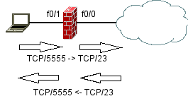
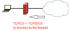
Reflexive Access Lists are cisco introduction to statefull filtering. For Firewalling it is a nice feature and can be thought as a kind of ip nat with overload without beeing able to reach the inside, only if you have trigged a connection from the inside, then traffic is allowed to pass.

Speaking of a established session, means the device in between records the connection and dynamically adds an allow filter to let the traffic matching to this session passing back through the firewall. That is the meaning of a statefull filter. Cisco standard and extended access-lists can only filter statically. Here is where reflexive access-lists come into play.

This are two configuration examples regarding telnet access for telnet sessions:

1. The first example allows telnet for established sessions in a „extended“ access-listinterface

ip access-list extended ESTABLISHED
permit tcp any eq telnet any established

FastEthernet0/0

ip access-group ESTABLISHED in

Here only telnet traffic originated from the inside client is allowed to come back into the network.

As you already expect there is another way with reflexive access-lists:

FastEthernet0/0

ip access-group REFL_IN in
ip access-group REFL_OUT out

ip access-list extended REFL_IN
evaluate REFLECT
ip access-list extended REFL_OUT
permit tcp any any eq telnet reflect REFLECT timeout 30

FW#sh access-lists

Reflexive IP access list REFLECT
permit tcp host 144.1.18.10 eq telnet host 144.1.5.5 eq 28929 (12 matches) (time left 25)

Extended IP access list REFL_IN
10 evaluate REFLECT
Extended IP access list REFL_OUT
10 permit tcp any any eq telnet reflect REFLECT (7 matches)

Here the host 144.1.18.10 is outside from firewalls perspective and is answering telnet requests from 144.1.5.5. This reflexive access-list is dynamically generated. By default this list is active for 300 seconds. If the connection is idle for that amount of time, the access-list is removed from the list and memory, but does not terminate the session. The active session will again bring up a new reflexive access-list. So this timeout has nothing to do with an absolut or idle timeout in the normal way of understanding idle timeout. It is more a „clean up“ timeout.

Here is a possible use of „ip tcp intercept“. vs. reflexive access-lis

ip tcp intercept list REFL_OUT
ip tcp intercept connection-timeout 20

Here you can set an idle timeout for the tcp connection in your firewall. The idle timeout is now set to 20 seconds.

R2#sh tcp intercept connections
Incomplete:
Client Server State Create Timeout Mode

Established:
Client Server State Create Timeout Mode
144.1.5.5:50346 144.1.18.10:23 ESTAB 00:00:59 00:00:01 I

After that time you can see your firewall sending an TCP Session Reset to both ends:

Packet debug on the firewall:

*Mar 1 10:37:00.665: IP: s=144.1.18.10 (local), d=144.1.5.5 (Vlan5), len 40, sending
*Mar 1 10:37:00.665: TCP src=23, dst=50346, seq=197049759, ack=1038522490, win=0 ACK RST
*Mar 1 10:37:00.665: IP: s=144.1.5.5 (local), d=144.1.18.10 (FastEthernet0/0), len 40, sending
*Mar 1 10:37:00.665: TCP src=50346, dst=23, seq=1038522490, ack=197049759, win=0 ACK RST
The connection is cleanly reset.

With ip tcp intercept you have more possible scenarios. For example if you are under a DOS Syn attack. Here i use nmap as a tool for generating multiple TCP SYN packets.

cat syn-dos-test.sh

nmap -sS -P0 -p 23 144.1.18.10 &

If you start this several times you will see ip tcp intercept starting some actions against half open sessions. High watermark is the point for starting aggressive mode and low watermark has to be crossed for starting normal mode again.

*Mar 1 13:50:35.548: %TCP-6-INTERCEPT: getting aggressive, count (5/5) 1 min 9
*Mar 1 13:50:35.548: INTERCEPT: Possible attack! Aborting half-open connection SYNRCVD (10.0.0.1:58971 <-> 144.1.18.10:23)
*Mar 1 13:50:35.548: INTERCEPT(*): (10.0.0.1:58971 <- RST 144.1.18.10:23)
*Mar 1 13:50:35.548: INTERCEPT: new connection (10.0.0.1:57671 SYN -> 144.1.18.10:23)
*Mar 1 13:50:35.548: INTERCEPT(*): (10.0.0.1:57671 <- ACK+SYN 144.1.18.10:23)
*Mar 1 13:50:35.584: INTERCEPT: Possible attack! Aborting half-open connection SYNRCVD (10.0.0.1:39401 <-> 144.1.18.10:23)

Now tcp intercept is starting to drop half open connections. Oldest first. You can also change the drop mode.

Next take a look at „ip inspect“ called CBAC (Context-Based Access Control).

interface FastEthernet0/0

ip access-group 101 in
ip inspect TELNET out

access-list 101 deny tcp any eq telnet any

ip inspect tcp idle-time 15
ip inspect name TELNET telnet

After opening a session, the telnet connection is able to establish and inspect has registred the session:

FW#sh ip inspect sessions
Established Sessions
Session 6571BC0C (144.1.5.5:12150)=>(144.1.18.10:23) telnet SIS_OPEN
Rack1SW2#

You can enable an idle timeout for telnet session:

ip inspect name TELNET telnet timeout 10

or for all tcp sessions:

ip inspect tcp idle-time 10

ip inspect max-incomplete low 4
ip inspect max-incomplete high 5
ip inspect name TELNET telnet alert on audit-trail off timeout 10


If you test the TCP Syn flood here also, you will get ip inspect react on the SYN Attack:

*Mar 1 14:24:43.736: %FW-4-ALERT_ON: getting aggressive, count (6/5) current 1-min rate: 6
*Mar 1 14:24:44.012: %FW-4-ALERT_OFF: calming down, count (3/4) current 1-min rate: 16

Audit-trail will log all connections/attempts. Alert will send only those to the log, which have been found suspicious.

CBAC does support many different protocols. Also protocols which negotiate ports dynamically. And is therefore able to inspect at the application layer.

Source:

http://www.cisco.com/en/US/docs/ios/security/configuration/guide/sec_cfg_tcp_intercpt_ps6350_TSD_Products_Configuration_Guide_Chapter.html#wp1001032

http://www.cisco.com/en/US/docs/ios/security/configuration/guide/sec_cfg_content_ac_ps6350_TSD_Products_Configuration_Guide_Chapter.html

29. November 2008

How to receive logging/traps with Linux from your dynamips with syslog-ng/snmptrapd

Filed under: Allgemein,IP and IOS Features,services — ocsic @ 20:06

What are traps and informs and is it possible to have a NMS (Network Managment System) on your Linux box to receive those messages? Cisco Works is also NMS, you might try this also, it’s possible to install it under VMWare, i had some trouble with 3.1 on Windows 2003 Server Enterprise SP2 though. Complaining always about not enough space on drive c:, however i expanded the disc to have more than 25GB of free space. Still no success. So i got to the point, where i dropped LMS and tried to use already present programs on my Linux box. Would like to see LMS also on my VMWare maybe later.

First make sure you have connectivity to the outside world from your dynamips. Here is a link to an more detailed description http://blog.sazza.de/?p=355. In short you need a local interface that can be bridged. You create a bridged interface and setup this with IP adressing. I use a VMWare interface for this bridged interface. Here is my script:

ifconfig vmnet7 0.0.0.0
ifconfig vmnet7 down
brctl addbr br0
ifconfig br0 10.0.0.1 netmask 255.255.255.0
brctl addif br0 vmnet7
brctl addif br0 tap0
ifconfig br0 up
ifconfig tap0 up
ifconfig vmnet7 up
The tap0 is created from your dynamips.net file. Is use Router1’s secound FastEthernt Interface:

[[Router R1]]
model = 3725
console = 2001
autostart = False
slot2 = NM-1FE-TX
slot1 = NM-4T
F0/0 = SW1 F1/1
F0/1 = NIO_tap:tap0
Now i can use R1 F0/1 for connections to the outside world.

Check your syslog-ng configuration file, to enable a socket your syslog server listens to port 514/udp:

/etc/syslog-ng/syslog-ng.conf

source src {
#
# include internal syslog-ng messages
# note: the internal() soure is required!
#
internal();

#
# the default log socket for local logging:
#
unix-dgram(„/dev/log“);

#
# uncomment to process log messages from network:
#
udp(ip(„0.0.0.0“) port(514));
};

Then restart your syslog daemon by issuing „/ect/init.d/syslog restart“. Make sure you can see the socket listening with

hostname:/usr/share/snmp/mibs # netstat -lun
Proto Recv-Q Send-Q Local Address Foreign Address State
udp 0 0 0.0.0.0:514 0.0.0.0:*
udp 0 0 0.0.0.0:162 0.0.0.0:*
udp 6624 0 0.0.0.0:68 0.0.0.0:*
udp 0 0 0.0.0.0:69 0.0.0.0:*

You might want do add port 514/tcp for syslog also listening to tcp logging messages. You can also log from your cisco router to any tcp port with:

R2(config)# logging host 10.0.0.1 transport tcp port 514

After this your system is able to recieve syslog messages und will log it into /var/log/messages for example. Check with „tail -f /var/log/messages“. Configure logging from a router with:

R2(config)# logging host 10.0.0.1

and produce some logging messages.

Next make sure that your local firewall does not block logging packets to your host.

You need at least ports:

514/udp

514/tcp

162/udp

At this point on your linux box start your

# snmptrapd -fa

You should have net-snmp-5.x.x installed (check with „rpm -qa | grep net-snmp“). This daemon also needs some kind of access configuration:

cat /etc/snmp/snmptrapd.conf

authCommunity log,execute,net CISCO
logoption f /var/log/snmptrapd.log
logoption s 2

/etc/snmp/snmpd.conf

mibs +ALL

Where CISCO is your community string. This is for SNMP v1 and v2c.

But you might want to download a list of MIBS from cisco first, to have snmptrapd support all kinds of cisco mibs. You can download them from ftp://ftp.cisco.com/pub/mibs/v1/v1.tar.gz and ftp://ftp.cisco.com/pub/mibs/v2/v2.tar.gz.

Just copy them to /usr/share/snmp/mibs (find out your mibs directory with „net-snmp-config –snmpconfpath“, where mibs should be a subdirectory, under your path for example /usr/share/snmp).

You should now be able to receive those mibs in your logfile /var/log/snmptrapd.log.

for example:

Nov 29 17:19:12 hostname snmptrapd[5824]: 10.0.0.2: Enterprise Specific Trap (.1) Uptime: 0:26:44.80, SNMPv2-SMI::enterprises.9.9.43.1.1.6.1.3.18 = INTEGER: 1, SNMPv2-SMI::enterprises.9.9.43.1.1.6.1.4.18 = INTEGER: 2, SNMPv2-SMI::enterprises.9.9.43.1.1.6.1.5.18 = INTEGER: 3

Or do an snmpwalk:

# snmpwalk -v2c -c CISCO 10.0.0.2

Reload your Cisco router with snmpset:

First enable system-reload:

snmp-server community CISCO RW
snmp-server system-shutdown

Then set the router ro reload (note dynamips router instance will crash, since reloading the router is only supported by dynagen console):

snmpset -c CISCO -v 2c 155.1.0.2  .1.3.6.1.4.1.9.2.9.9.0 i 2

Source:

http://www.net-snmp.org/wiki/index.php/TUT:Configuring_snmptrapd

http://www.net-snmp.org/wiki/index.php/TUT:Configuring_snmptrapd_to_receive_SNMPv3_notifications

http://www.net-snmp.org/wiki/index.php/TUT:Configuring_snmptrapd_to_parse_MIBS_from_3rd_party_Vendors

http://www.net-snmp.org/wiki/index.php/TUT:Using_and_loading_MIBS

http://tools.cisco.com/ITDIT/MIBS/servlet/index

4. November 2008

ip prefix-list

Filed under: IGP Routing,IP and IOS Features — ocsic @ 12:35

I had to look at prefix-lists again a bit more in detail and how matching is done.

There are several key words that need to be understood for mathing the right addresses.

At first the most simple match is the:

ip prefix-list PRE_20 permit 20.0.0.0/24

which does just match for the first 24 bit in the address and nothing else.

If in case you have to match more addresses, maybe a range from subnets with a specific prefix, you can match it with „ge“ or „le“.

„ge“ means greater or equal

„le“ means less or equal

So if you want to match the following subnets:

20.0.0.0/16

20.1.0.0/16

You could create an prefix list with the following match:

ip prefix-list PRE_20 permit 20.0.0.0/15 ge 16 le 16

This means, that first the matching is done one the subnet that is the same for all subnets: 20.0.0.0/15, that can include 20.0.0.0 and 20.1.0.0.

Here we already summarized the best match for both addresses. So this part is the same for all addresses. Then, since we don’t want to match the 20.0.0.0/15 or the 20.1.0.0/15, we have to tell the prefix list, how to extend the variable match for addresse, that should be included in the match.

Se we want specially matches greater or equal /16 and maximal /16.

That means:

ip prefix-list PRE_20 permit 20.0.0.0/15 ge 16 le 16

If we want to include for example only:

20.0.0.0/24

20.0.1.0/24

20.0.2.0/24

20.0.3.0/24

ip prefix-list PRE_22 permit 20.0.0.0/22 ge 24 le 24

Another example would be to match a range of subnets with „le“

ip prefix-list 20.0.0.0/16 le 18

Would match:

20.0.0.0/16

20.0.0.0/17

20.0.0.0/18

Where the 20.0. prefix must be in all network ranges at a minimum and every address with a maximum of /18 would match if 20.0. is in the prefix.

10. Juli 2008

ip default-network vs. ip default-gateway

Filed under: IGP Routing,IP and IOS Features — ocsic @ 12:58

Every time a come across these commands i wonder what is the difference. Now i have looked it up … 🙂

„ip route 0.0.0.0 0.0.0.0 x.x.x.x“ and „ip default-network x.x.x.x“ are the same. They are used when „ip routing“ is enabled. If not use „ip default-gateway x.x.x.x“.

If you add the ip default-network command in EIGRP, you will see the D* in your routing table, as the candidate default. Even if this is not a route to null, it will be used from all routers as it. Seems like a remaining, from the IGRP times, when no summary with 0.0.0.0 0.0.0.0 was possible.

Source:

http://www.cisco.com/en/US/tech/tk365/technologies_q_and_a_item09186a008012d8f7.shtml#qa7

http://www.cisco.com/en/US/tech/tk365/technologies_tech_note09186a0080094374.shtml

12. Januar 2007

ntp auth

Filed under: IP and IOS Features — ocsic @ 15:49

Server 192.10.1.254 with authentication

Rack1R1#s | inc ntp
ntp authentication-key 1 md5 02252D682829 7
ntp authenticate
ntp trusted-key 1
ntp server 192.10.1.254 key 1

Rack1R1#sh ntp ass de
192.10.1.254 configured, authenticated, our_master, sane, valid, stratum 4
ref ID 127.127.7.1, time AF7D0BB5.1F58ABC8 (11:29:57.122 UTC Mon Apr 19 1993)
our mode client, peer mode server, our poll intvl 64, peer poll intvl 64
root delay 0.00 msec, root disp 0.03, reach 360, sync dist 3.479
delay 6.52 msec, offset -0.1136 msec, dispersion 16000.00
precision 2**18, version 3
org time AF7D0BBA.91DA71F5 (11:30:02.569 UTC Mon Apr 19 1993)
rcv time AF7D0BBA.92AD5CD9 (11:30:02.572 UTC Mon Apr 19 1993)
xmt time AF7D0BBA.903C38FA (11:30:02.563 UTC Mon Apr 19 1993)
filtdelay = 0.00 0.00 7.51 6.52 6.73 9.09 7.35 7.02
filtoffset = 0.00 0.00 0.44 -0.11 -0.04 1.14 0.03 -0.10
filterror = 16000.0 16000.0 0.08 0.09 0.11 0.12 0.14 0.15

configuring access to ntp servers
if acting as an ntp server only for clients in the access-list 1
ntp access-group serve-only 1

30. November 2006

What’s the difference between „ntp server“ and „ntp peer“?

Filed under: IP and IOS Features — ocsic @ 10:56

There are three possible relationships that ntp can establish.

  • client-server
  • peer-peer
  • sending broadcasts

With „ntp server“ only the client can get the time from the server.

With „ntp peer“ there is a peering relationship established and both can get the time from each other, regarding to the lower stratum.

As for example, i have router A, B and C. B is configured as a clients of A with „ntp server A“.

So A will provide the time for B. B will only get the time from A.

C is configured with „ntp peer B“. So C and B will share time information and can syncronize to each other, depending on which one has a better stratum.

All routers configured with the peer command can be „bound“ together inside a full mesh, where then every router is participating in the best time sync.

6. August 2006

3550 IOS recovery

Filed under: IP and IOS Features — ocsic @ 21:04

The 3550 Catalyst switch does not have IOS recovery functions other than xmodem, when the IOS is lost due to corruption or maybe user error. You have to copy it with xmodem back to the switch. I would suggest, taking a smaller image first, because this take quite a long time. For an 3,5 MB sized image, it would take 1 hour and 10 Minutes.

Boot the switch with the missing IOS. Start the command:

switch: copy xmodem: flash:new-filename.bin

And then start Hyperterminal and send the binary file from your local harddisc via xmodem.
Source:

http://www.cisco.com/en/US/products/hw/switches/ps628/products_tech_note09186a0080169696.shtml

22. Juli 2006

NAT, PAT, overload, RFC 1631

Filed under: IP and IOS Features — ocsic @ 09:42

Network Address Translation

NAT has developed because of short address spaces on the internet. There is no reason why LAN’s should have globally reachable IP addresses. So private address space is used in local LAN. And at the boarder router, addresses are translated into globally valid ip addresse. There can be many different kinds of mapping. For example you can map a number of local LAN addresses to one global address. N -> 1 Or you can map a group of local addresses to a group of global addresses N -> M. The special N -> 1 mapping is called „overload“ at cisco devices. Also clalled PAT (Port Address Transloation). Differnet inside addresses are mapped to one outside address over different TCP port mappings.
First important thing is to know about the mapping included with NAT. Cisco speaks of inside local, inside global, outside local and outside global mappings.

It’s important to know these terms good.

At first you have to decide witch interface is outside and witch is inside. The outside interface is for example the side connected to the WAN.
For understanding, keep in mind, local IP addresses are seen in the inside world and global IP addresses are seen in the outside world.

Here is an picture of these definitions and a description for a static overload definition.

static overload NAT

Here are the definitions for the NAT router:

ip nat inside source list 1 interface Serial0/0 overload

Where serial0/0 is the outside interface. You can also set the ip address of the outside interface:

ip nat inside source list 1 interface 192.168.1.1 overload

Source list is an defined access list. This would be any addresses you would like to participate in port address translation:

access-list 1 permit 1.1.1.0 0.0.0.255

This would allow the subnet 1.1.1.0 to be translated to the outside with ip add 192.168.1.1.
Don’t forget to set on the inside interface:

interface ethernet0/0

ip nat inside

and on the outside interface:

interface serial0/0

ip nat outside
This is what is also called PAT (Port Address Translation).
The logic behind this, is a little bit different from what happens on a linux system for example. In the cisco world you sit in between the interfaces. In the linux world with iptables you concentrate on one interface and define most definitions there. Well there is not that much difference, but for me it was a kind of new, to understand cisco NAT.

The following solutions are possible:

static NAT:

it’s a one to one mapping. One indide address can be translated to one outside address.

Or PAT is possible. This is many inside addresses to one outside address.

dynamic NAT:

a group of inside addresses can be translated to a group or pool of outside addresses.

match host:

To assign the same host portion to an translated address. The network portion stays the same. For example to translate the address 1.1.1.1/16 to 192.168.1.1/16.

Source:

http://www.cisco.com/en/US/tech/tk648/tk361/technologies_white_paper09186a0080091cb9.shtml

http://www.ietf.org/rfc/rfc1631.txt?number=1631

21. Juli 2006

HSRP => Hot Standby Router Protocol

Filed under: IP and IOS Features — ocsic @ 10:25

HSRP = HOT Standby Router Protocol

This protocol provides redundancy in case a router is not more available, by emulating a virtual router. This virtual router can consist of many other routers depending on how many are setup for redundancy. At least there have to be two routers configured for redundancy.

MHSRP is Multi Group Hot Standby Router Protocol. It can be used for load sharing.

MHSRP
This configuration is an example for MHSRP.

R1 config:

interface e0

ip add 192.168.1.30 255.255.255.0
standby 1 preempt
standby 1 priority 110
standby 1 ip 192.168.1.100
standby 1 track serial0 120
standby 2 preempt
standby 2 ip 192.168.1.200

R2 config:

interface e0

ip address 192.168.1.31 255.255.255.0
standby 1 ip 192.168.1.100
standby 1 preempt
standby 2 ip 192.168.1.200
standby 2 priority 110
standby 2 preempt
standby 2 track serial0 120

Explanation:

The default prio for an interface is 110. So for 1.100 R1 has by default active state. For 1.200 it’s router 2. The track parameter change the prio, so if an serial interface goes down, the prio is changed, the means decremented by the value configured. So then the other interface with the higher value goes into active state.

You can watch state change from „Standby -> Active“ if a serial0 interface comes back again. And the other side reactes with:

02:21:09: %HSRP-6-STATECHANGE: Ethernet0/0 Grp 1 state Active -> Speak
02:21:19: %HSRP-6-STATECHANGE: Ethernet0/0 Grp 1 state Speak -> Standby

And goes to standby again.

If a serial0 interface goes down, the other side imediately goes into active state:

06:50:01: %HSRP-6-STATECHANGE: Ethernet0/0 Grp 2 state Standby -> Active

and the other router reacts with:

02:22:41: %HSRP-6-STATECHANGE: Ethernet0/0 Grp 2 state Active -> Speak
02:22:51: %HSRP-6-STATECHANGE: Ethernet0/0 Grp 2 state Speak -> Standby

Pay attention. A really pitfall i have meet, was that with my old 2500’er router and the AUI – ethernet Transiver/Adapter, it was not possbile to configure MHSRP. There seems to be a problem with the mac address handling. Although i could set it up, it does not work and there are no error messages and it works partly. But if you try to have more than one group active on the 2500’er, that does not work. Took me three hours, after that i changed the 2500’er with a 2600’er and i worked like a charm.
Source:

HSRP Load sharing

http://www.cisco.com/warp/public/619/7.html

HSRP Technology:

http://www.cisco.com/en/US/tech/tk648/tk362/tk321/tsd_technology_support_sub-protocol_home.html

Older Posts »

Powered by WordPress